30+ inverter circuit block diagram
Uninterruptible power supply have very core importance for control of sensitive devices such as computers induction machines medical equipments and many other things. Abbreviated with the letter C.

Three Phase Inverter Circuit Working And Its Applications
Inverters do the opposite of rectifiers which were originally large electromechanical devices converting AC to DC.

. There are many basic electrical circuits for the power. When there is a lightning strike high voltage is generated through the power grid. 6902 DefinitionsPV Output Circuit Inverter Input Circuit1 ½ pages of PV-specific jargon.
270 MINI ELECTRONICS PROJECT WITH CIRCUIT DIAGRAM. June 18 2015 at 330 pm Dear Bilal I like your blog thank you. Silent Knight 6820 Manual.
Design and Phase Frequency Detector Using Different Logic Gates in CMOS Process Technology. So a CMOS inverter is a very simple circuit designed with two opposite-polarity MOSFETs within a complementary way. A power inverter inverter or invertor is a power electronic device or circuitry that changes direct current DC to alternating current AC.
A basic inverter circuit is used to accomplish a logic variable by complementing from A to A. COMPANDING CIRCUIT USING OPAMPS. The engine block is the main part of an.
The inverter is accepted universally as the basic logic gate while performing a Boolean operation on a single ip variable. These inverters have two conduction modes such as 120-mode of conduction 180 mode of conduction. Sine wave inverter circuit diagram using microcontroller Arduino and program code SPWM using pic16f877a microcontroller.
Considered up to 30 dB. The output of the smps is regulated by means of PWM Pulse-Width-Modulation. The different parts that make up your cars engine consist of the engine block cylinder block the combustion chamber the cylinder head pistons the crankshaft the camshaft the timing chain the valve train valves rocker arms pushrodslifters fuel injectors and spark plugs.
DESIGN OF OP AMP USING CMOS WITH. You just have to program the arduino board. Circuit Diagram Of Smps Power Supply DC-DC.
① Lightning Protection Circuit. The internal resistors act as a voltage divider network providing 23Vcc at the non-inverting terminal of the upper comparator and 13Vcc at the inverting terminal of the lower comparator. Mr pleese 100w inweter circuit ferrit core trans.
DC boost circuit using 555 timer. You are talking about the inverter circuit converting DC into 110220v AC check this circuit. The 3-single phase inverters place across the similar DC source and the pole voltages within a 3-phase inverter are equivalent to the pole voltages within 1-phase half-bridge inverter.
Design of Astable Multivibrator Circuit. It is applicable as a filter that is to block DC signals and allow AC signals. Part Time Camper.
In most applications the control input is not used so that the control voltage equals 23 V CC. Block Diagram of Switching Power Supply Circuit. How To Wire A Battery.
Of 24-Volts and operating at about 30 Volts. The input voltage output voltage and. Here is a interesting circuit by drea mlover technology.
Schematic of Input Filter Rectifier Circuit. Inverter Install And Dual Battery Setup In His Ford wwwdfnainfo. Design and Modelling of Notch Filter using Universal Filter FLT U2.
Uninterruptible power supply also used in many countries where energy shortage is a main issue. It consists of two metals plates that are separated by a dielectric. 12v DC to 220v AC Inverter Circuit.
Block diagram of PV system without battery backup. I have also added practical circuit for UPS in this article. Decoder and its Analysis.
Refer Block Diagram of 555 timer IC given above. Submitted by Parag on Mon 06202016 - 1530. Wiring ingersoll hersee.
Derivatives provide two or four timing circuits in one packageThe design was first marketed in 1972 by Signetics. I have taken the liberty of attaching an image of a quasi-block diagram of my tentative design for your consideration. Since then numerous companies have made the original bipolar timers as well as similar low-power CMOS timers.
In the last article we learned how to generate sine wave pulse width modulation or SPWM though Arduino we are going to use the same Arduino board to make the proposed simple pure sine wave inverter circuitThe design is actually extremely straightforward as shown in the following figure. I have gone through your block on the spwm programming. The resulting AC frequency obtained depends on the particular device employed.
Ⅳ Principle of Input Circuit and Common Circuit 41 Principle of AC Input Rectification and Filtering Circuit. As given in the circuit above the switch can be driven by the PWM-oscillator such that the power delivered to the step-down transformer is controlled indirectly hence the output is controlled by the pulse-width-modulation as this. Here is the complete circuit diagram for cell phone charger circuit.
A very effective pure sine wave inverter circuit can be made using the IC 4047 and a couple IC 555 together with a few other passive components. June 30 2022 at 907 am. The 555 timer IC is an integrated circuit chip used in a variety of timer delay pulse generation and oscillator applications.
The only downside to this is now my fuse block circuit becomes an 80 amp max. Capacitor is a device that is used to store electrical energy.

This Article Briefly Describes The 30 Watt Audio Power Amplifier Irf9530 This Principle Is Easy To Understa Power Amplifiers Audio Amplifier Circuit Diagram

Wiring Theory For Contactors Dc Dc Conv Charger Diy Electric Car Forums

The Simplest Function Generator Built On A Breadboard Function Generator Generator Circuit Diagram

Let S Try To Work Out The Proposed 500va Pure Sine Wave Inverter Circuit Layout Elaborately With The Electronic Schematics Sine Wave Electrical Circuit Diagram

Half Bridge Inverter Circuit Diagram Advantages Its Disadvantages

Diy Solar Projects For The Home Online Workshop Solar Water Heater Diy Solar Energy Projects Solar Energy Diy

Charge Control Diagram For Wind Turbine Solar Panel System Solar Energy Solutions Diy Wind Turbine Solar Energy Projects

Short Circuit And Over Voltage Protection Basics In Circuits

Mp2208 Converters 16v 4a 600khz Synchronous Step Down Converter Mps Monolithic Power Systems

Pin On Class D Amplifier

Current Source Inverter Circuit Diagram And Its Advantages

30 0 30 Volt 500w Switching Power Supply For Power Amplifier Youtube Power Supply Circuit Power Amplifiers Circuit Diagram

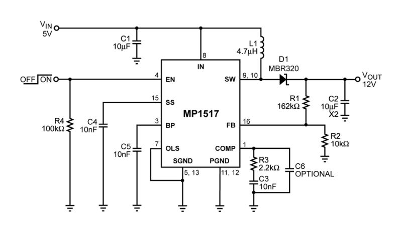
Mp1517 3a 25v 1 1mhz Step Up Converter Mps

Inverters Working Different Types Circuit Working And Its Applications

Pwm Inverter Definition Circuit Diagram Working And Applications

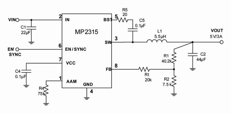
Mp2315 High Efficiency 3a 24v 500khz With Aam Light Load Mode Synchronous Step Down Converter In Tsot23 8 Mps

Reasons For Using Contactors Diy Electric Car Forums